
Detector Operation
This chapter describes the process of operating the detectors with a computer interface.
Setting Up the Detectors
The superconducting nanowire detectors operate by applying a DC bias current (known as Device Bias) slightly below a threshold "switching current." Upon absorption of a photon, the nanowire switches from a low-resistance superconducting state to a high-resistance "normal," or non-superconducting, state resulting in rapid increase in output voltage. The detector recovers after a "recovery time." In a standard system, the bias current to each detector is supplied through the electrical connections to the "Nanowire" port of the respective QOELEC channel. The voltage pulses generated by photodetection are amplified by integrated electronics in integrated systems or by the QOELEC in standard systems, and output from the corresponding "Pulse Out" port.
For Integrated Systems
- Using a 50 Ω-impedance, low-noise cable, connect the relevant channel "Pulse Out" SMB connector to a pulse counter with a 50 Ω input impedance. For the standard TTL option system set the counter to trigger on rising-edge pulses with a threshold of 500 mV.
- If the system is cold, the device is now ready for use. To test if the device is functioning, remove the fiber cap to let ambient light into the biased channel. At this point, you should see a significant increase in the measured count rate.
- If ambient light does not increase in the measured count-rate, the first troubleshooting steps are as below.
- Install and launch the Quantum Opus Control Panel software.
- Plug in a USB cable from your computer to the Opus One. Verify the USB status LED turns green.
- Verify the system is cold, and bias is turned on for the relevant channel
Instructions on obtaining and installing this software are available on our website in the Support section. More detailed instructions for the sample web interface are given below in Section 5.2.
Scientists at Quantum Opus enjoy helping you optimize the system for your application, so please reach out to us for any desired assistance.
For Standard Systems
After properly connecting all Opus One nanowire channels to the QOELEC (see Chapter 3), use the following steps to bias and operate each device.
Using a 50 Ω-impedance, low-noise cable, connect the QOELEC channel "Pulse Out" SMA connector to a pulse counter with a 50 Ω input impedance. For a system with no cryogenic amplifier set the counter to trigger on rising-edge pulses with a threshold of +75 mV. For systems with the cryogenic amplifier option set the threshold to falling-edge pulses with a threshold of −500 mV. For the TTL output option, set the threshold to rising-edge with a threshold of 500 mV.
The counter should read zero counts per second of electrical noise at this point. If you are seeing high counts, there is likely a ground issue or electrical noise from the lab environment. Please see Chapter 6 for advice on how to correct this electrical interference.
Install and launch the QOELEC Control Panel software. Instructions on obtaining and installing this software are available on our website in the Support section. More detailed instructions for the sample web interface are given below in Section 5.2.
Setting the Device Bias: With the fiber input port on the Opus One capped, gradually increase the device bias until the dark counts are at the highest acceptable level (typically a few hundred counts per second). Both device efficiency and dark counts slightly increase as you increase the bias, so the optimal bias point will vary by application.
The device is now ready for use. To test if the device is functioning, remove the fiber cap to let ambient light into the biased channel. At this point, you should see a significant increase in the measured count rate.
Scientists at Quantum Opus enjoy helping you optimize the system for your application, so please reach out to us for any desired assistance.
Web Interface
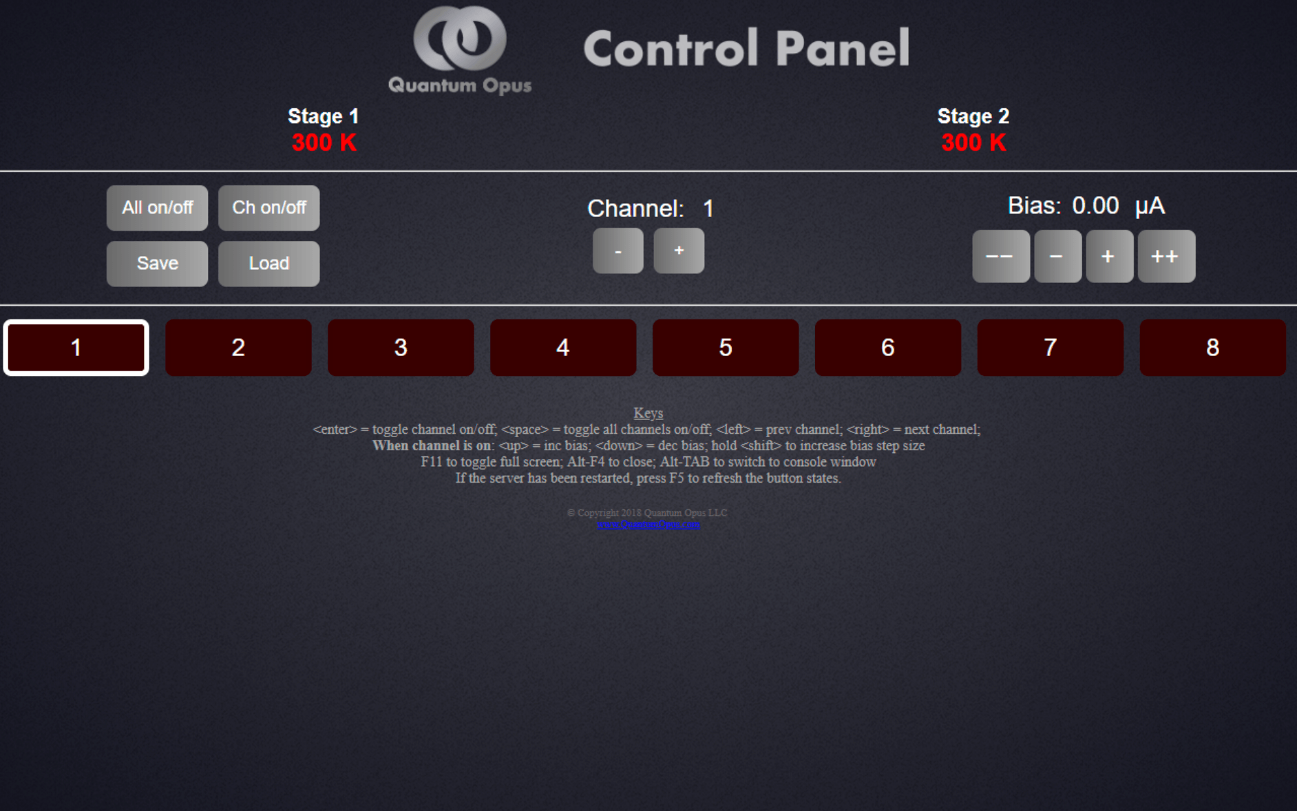
Both the integrated electronics and QOELEC can be controlled using a computer interface. A sample web-based interface with associated Python, HTML, and JavaScript code may be provided upon request. The following list of basic operations may be performed using this interface.
- All on/off
Press the button to turn on or off all channels.
- Ch on/off
Each channel has a corresponding button. Press the button to turn on the desired channel(s). When it is highlighted green, the channel is on. Each channel stores the most recently set device bias. If the button is pressed to turn off the channel after setting a bias, when turned back on, it will set the previously chosen bias.
Press the plus (+) button or the minus (-) to increase or decrease respectively the channel number being controlled with the bias and channel on/off buttons.
Press the plus (+) button or the (++) to increase the bias current. The (+) button has a bias increment of approximately 1% of the present bias setting, while the (++) button has a bias increment of approximately 10%. Holding either button will rapidly increase the bias.
- Save Bias:
When all channels are turned on with their respective biases (at the same time), press the Save button. This will store all of the biases to their respective channels.
- Load Bias:
Press the Load button to load previously stored biases.
Keyboard Operation - The above functions may be activated by keyboard if available.
Right and left arrow keys move between channels.
Up and down arrow keys increment and decrement the bias of the selected channel; holding Shift while pressing up/down arrows will change bias in larger steps.
Enter toggles the On/Off state of the selected channel.
Space bar toggles all channels On/Off.