
Installation
This section covers unpacking and installing your new nanowire detector system.
For Portable Systems
Preparation for Cooldown
If a front cover is attached (refer to Figure 7), to protect the optical, electrical, communication, and One-Button user interfaces, loosen (do not remove) the bolts securing it using a 4mm hex key, lift the cover slightly, pull it off from the front of the system, then re-tighten the bolts.
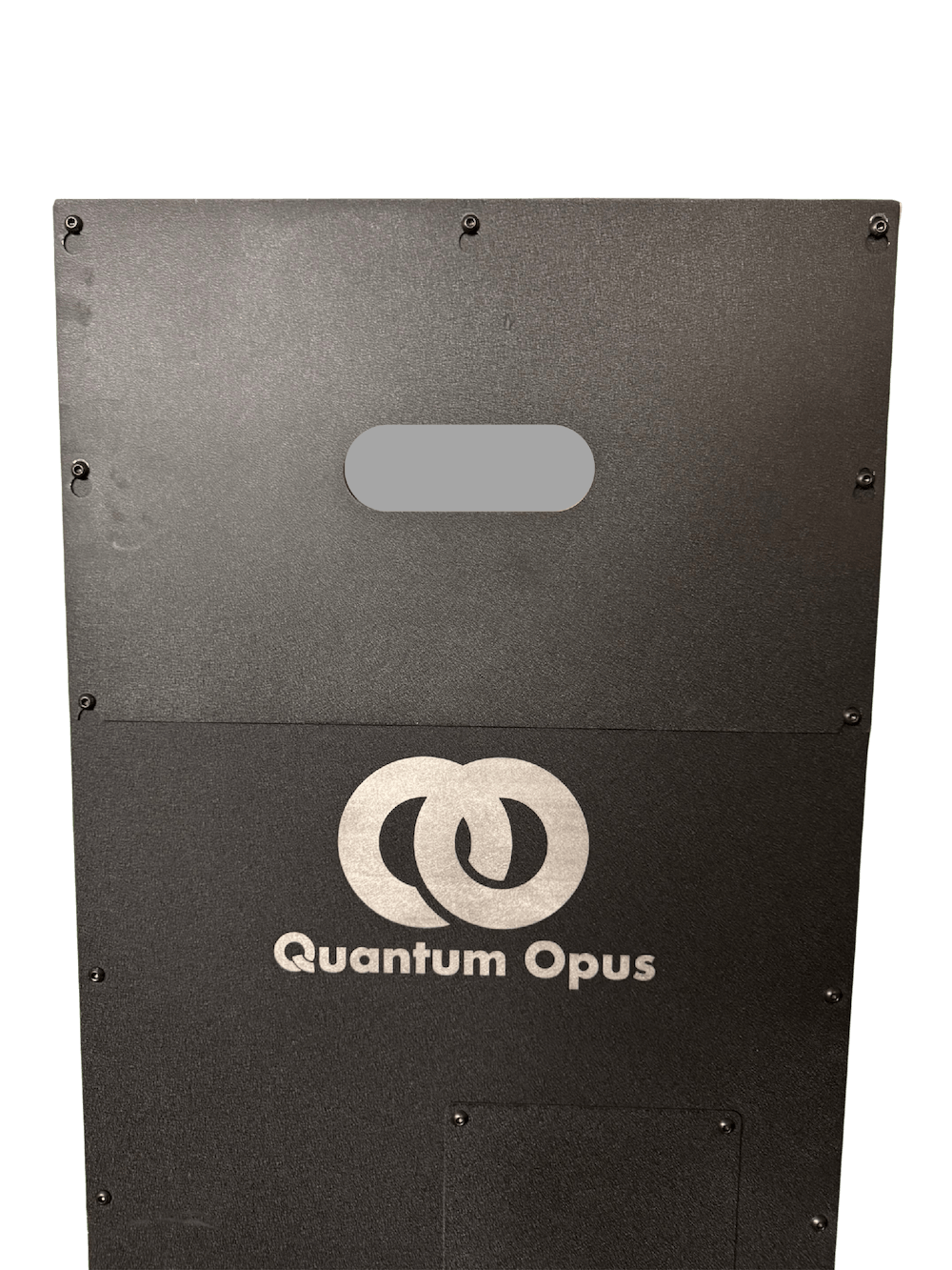 Figure 7: Shipping cover for Portable Systems
Review the voltage and frequency specification listed on the QR code sticker on the back of the unit and confirm the availability of a suitable outlet.
Plug the power cable into back of the Opus One Portable unit and plug the other end into the electrical outlet.
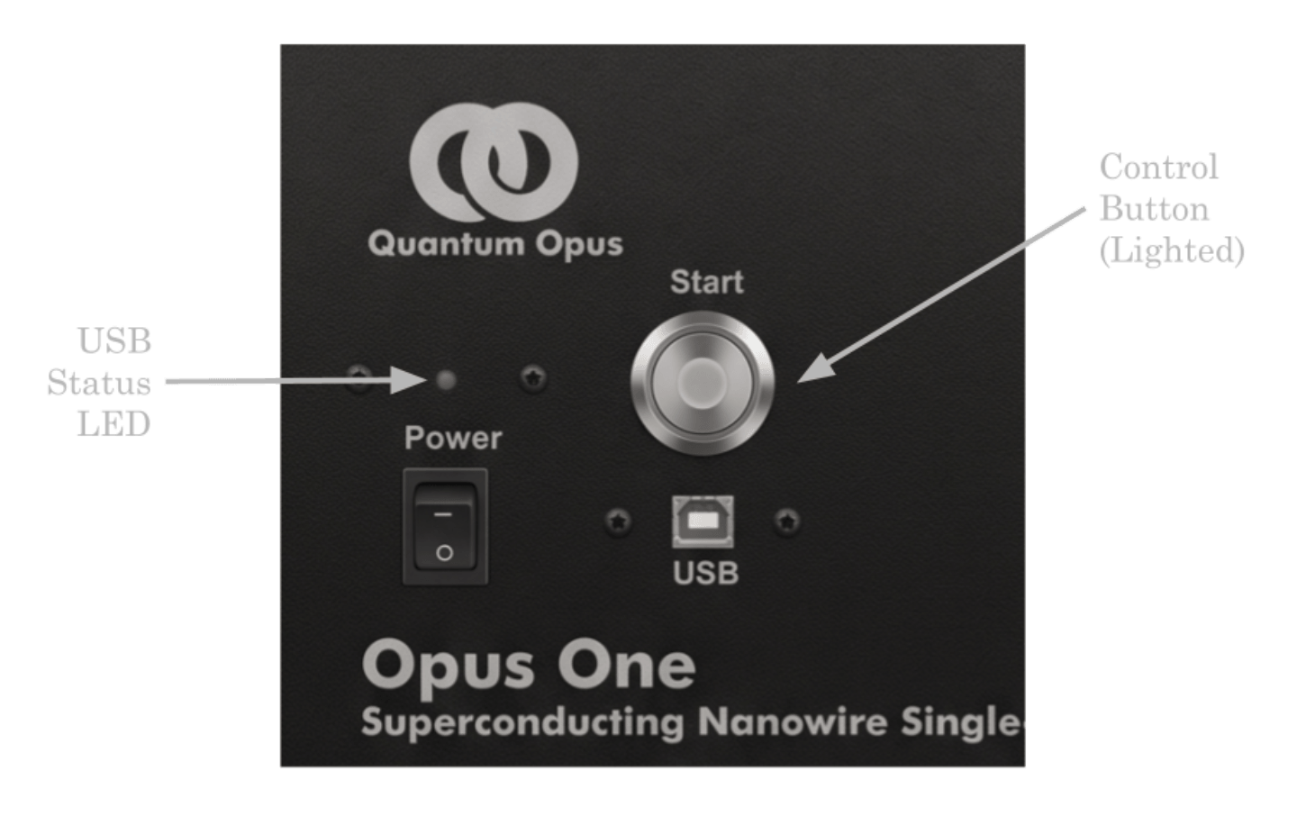
With the electronics switched on, the control button will light up green, and the small status LED should turn orange if the unit is not connected via USB. Refer to Figure 8 on the next page for LED and switch layout.
For Non-Portable Systems
Preparation for Installation
Before unpacking your Opus One unit, ready the compressor unit. Carefully consider the placeent of the compressor and Opus One. Refer to Figure 4 or Figure 5 for layout.
Determine compressor and high-pressure helium location appropriate for proper proximity to your water and power connections.
Determine the Opus One unit location appropriate for your source of photons, ensuring
that the helium lines can move freely and will not be under tension. Minimize the distance
between your optical source and the detector unit.
Compressor Unit Installation
Establish the proper electrical and water connections to the compressor according to documentation provided separately by the compressor manufacturer. Be sure to comply with all manufacturer recommendations and local laws, codes, and building recommendations.
Perform any recommended compressor run testing. See provided compressor manufacturer documentation.
After any required compressor run testing, install the high-pressure helium lines onto the compressor SUPPLY and RETURN connections and the drive cable, as described in the compressor manufacturer documentation.
Opus One Unit Installation
Lift and position the Opus One according to the following guidelines. Avoid lifting by any valve, port, electrical, or tubing connections. As long as you avoid the tubing lines, you may lift by the central solid aluminum block at the rear of the unit, as shown in Figure 9.
Carefully remove the Opus One unit from its packaging. Note that the unit has a significant fraction of its weight toward the back. It is critical that the unit remain horizontal.
Remove any protective wrapping around the Opus One unit and on the front panel.
For rack-mount operation, it is essential to support both the front and back of the system using a shelf which is rated for at least 500 lb or 225 kg, although your Opus One unit only weighs about 50 pounds, to account for dynamic loads such as those that may occur during seismic activity or other unforeseen loading conditions. Contact Quantum Opus support for guidance on the selection of an appropriate shelf mount.
If desired, apply the provided adhesive feet near the corners of the bottom panel of the Opus One.
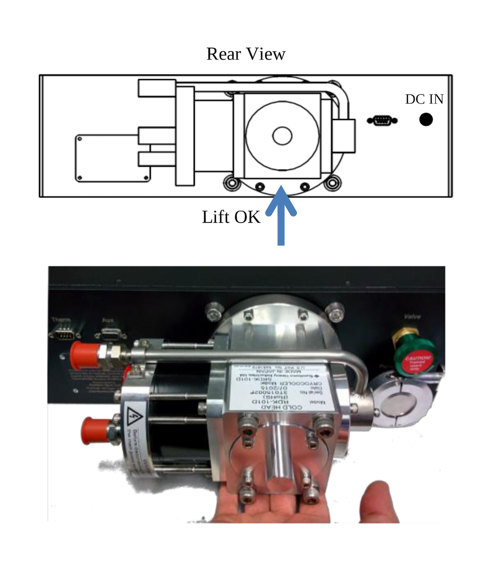 Figure 9: Rear view of the Opus One Integrated unit with built in vacuum pump showing a suggested lift point for installation.
Ensure any temporary or final location is chosen such that, after the high-pressure helium lines are connected, strain on the high-pressure helium connections at the rear of the unit is minimized.
The pressurized helium lines must be connected in the following order.
Ensure the SUPPLY and RETURN lines are already connected to the compressor and properly labeled SUPPLY and RETURN.
If (optional) pressurized right-angle adapters are to be used, contact Quantum Opus for the proper installation procedure.
First, using the proper “three-wrench” procedure as illustrated on page 26 of the Sumitomo Cryocooler Operations Manual (available in the Support section of our website), connect the “RETURN” high-pressure helium line to the “RETURN” connector on the rear of the Opus One unit.
Second, again using the proper “three-wrench” procedure, connect the “SUPPLY” high-pressure helium line to the “SUPPLY” connector on the rear of the Opus One unit.
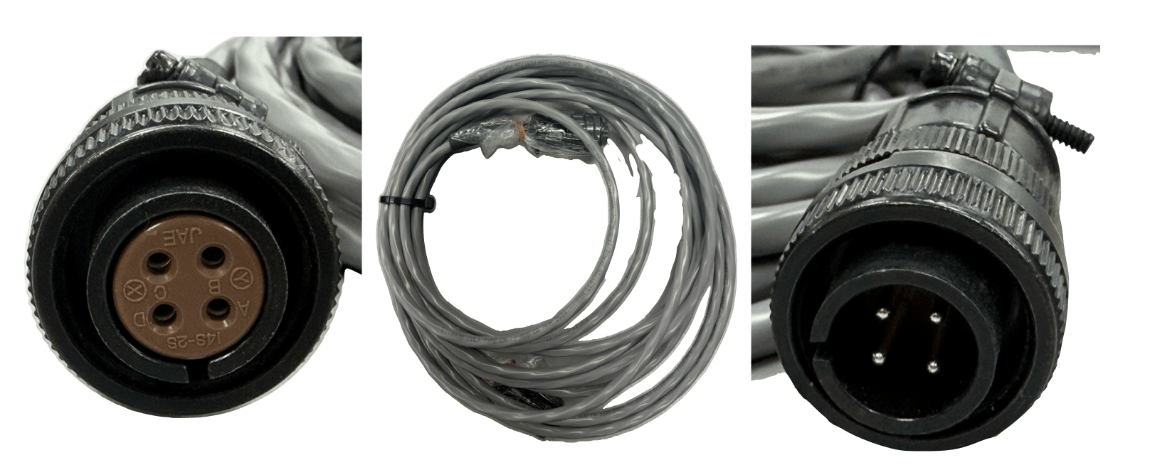
Connect the provided electrical cold head drive cable between the compressor and the
Opus One unit. Refer to Figure 10 and Figure 11 to identify the correct cable.
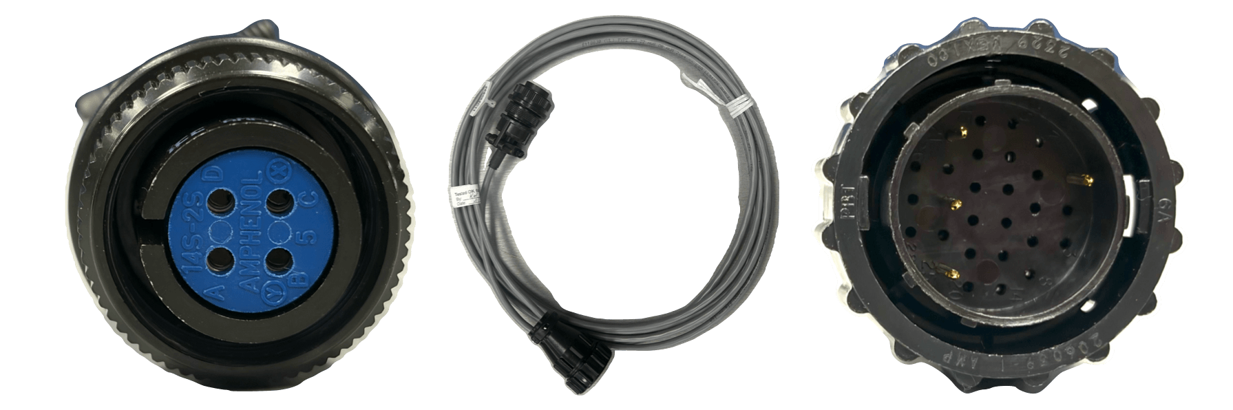
Compressor and Vaccum Pump Setup for Opus One Integrated Units
Opus One Integrated units have integrated compressor control relays. In addition to connecting the cable, the compressor switches must be set properly for remote operation as follows. The same is true for the remotely operated vacuum pump. Refer to Figure 13 on the next page to help you locate the DB-9 Connector on the Opus One integrated unit for the compressor control.
For the Air Cooled CNA-11C Compressor
Use the included DB-9 to DB-15 Cable to attach the Opus One Electronics from the to
the Compressor. The DB-9 end attaches to the opus one port labeled “Compressor”. Refer to Figure 14.Ensure the “Remote Drive Switch” is in the “EXT” position. Refer to figure 15
Ensure “Cold Head Drive Switch” is in the “OFF” position. Refer to figure 15
Rotate the rotary transformer breaker to the “ON” position. Refer to figure 16
Set “Main Power Switch” to the “On” position. Refer to figure 17
Set “Drive Switch” on the front of the compressor to the “On” position. Refer to figure 18.
For the Water Cooled F20L Compressor
Use the included control cable with module to connect the DB-9 connector on the Opus One to the receptacle for remote on/off on the compressor. The DB-9 end attaches to the opus one port labeled “Compressor”. Refer to Figure 19.
Ensure “Local ON/OFF Switch” is in the “Off” position. Refer to figure 20.
Ensure “50/60 HZ Toggle Switch” is in the correct position for the power frequency supplied. Refer to figure 20.
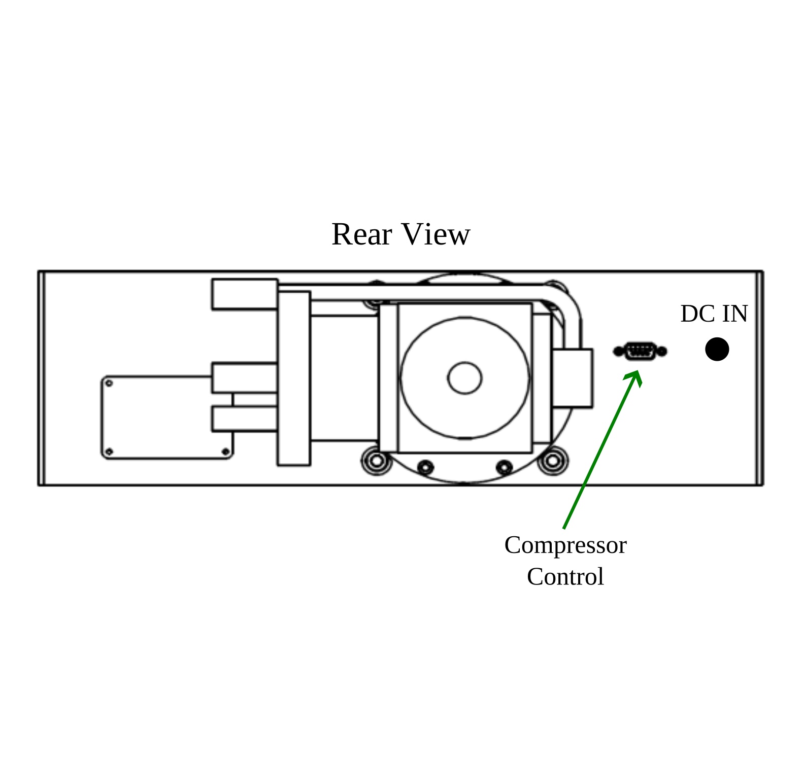 Figure 12: Opus One with External Vacuum Pump.
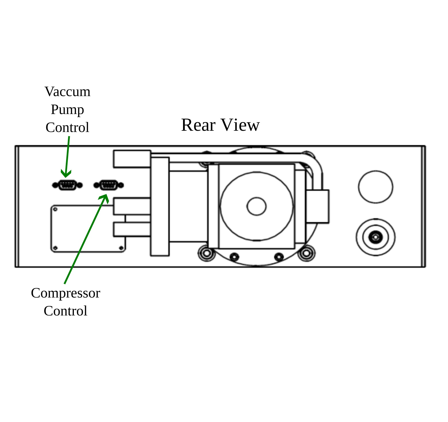 Figure 13: Opus One with Internal Vacuum Pump.
Switch the “20A Circuit Breaker” to the “On” position. Refer to figure 20.
For the Water Cooled HC-4E1 and HC-4E2 Compressor
Use the included control cable with module to connect the DB-9 connector on the Opus One to the receptacle for auxiliary power and remote on/off on the compressor. The DB-9 end attaches to the Opus One port labeled “Compressor”. Refer to Figure 19.
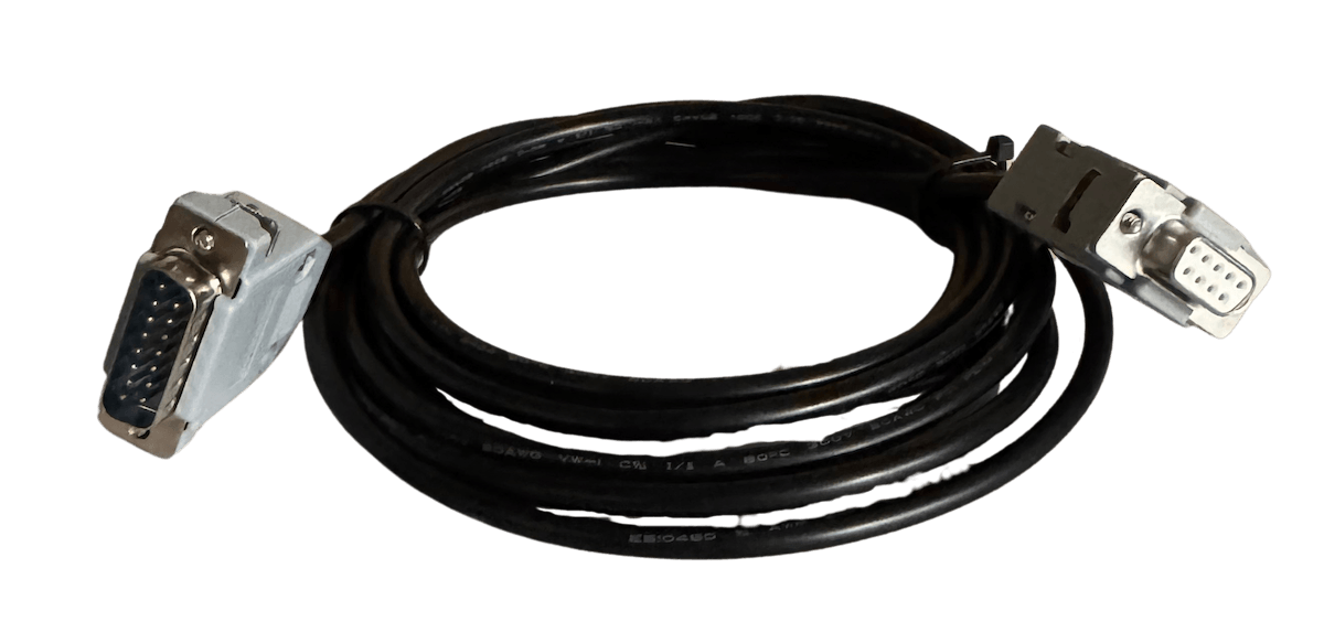 Figure 14: DB-9 to DB-15 Remote Compressor Control Cable.
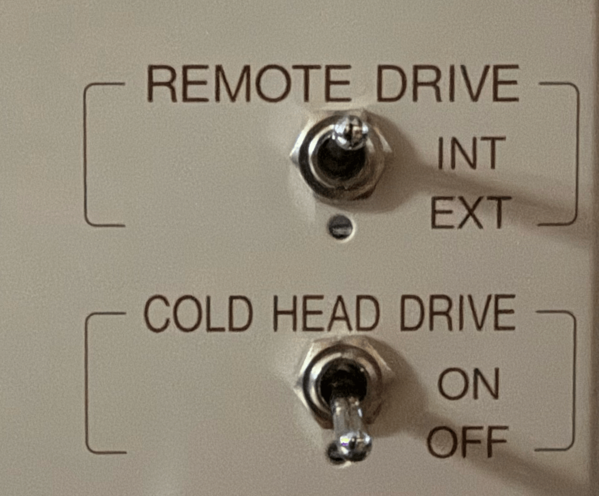 Figure 15: Remote & Cold Head Drive Switches for Air Compressor with integrated system.
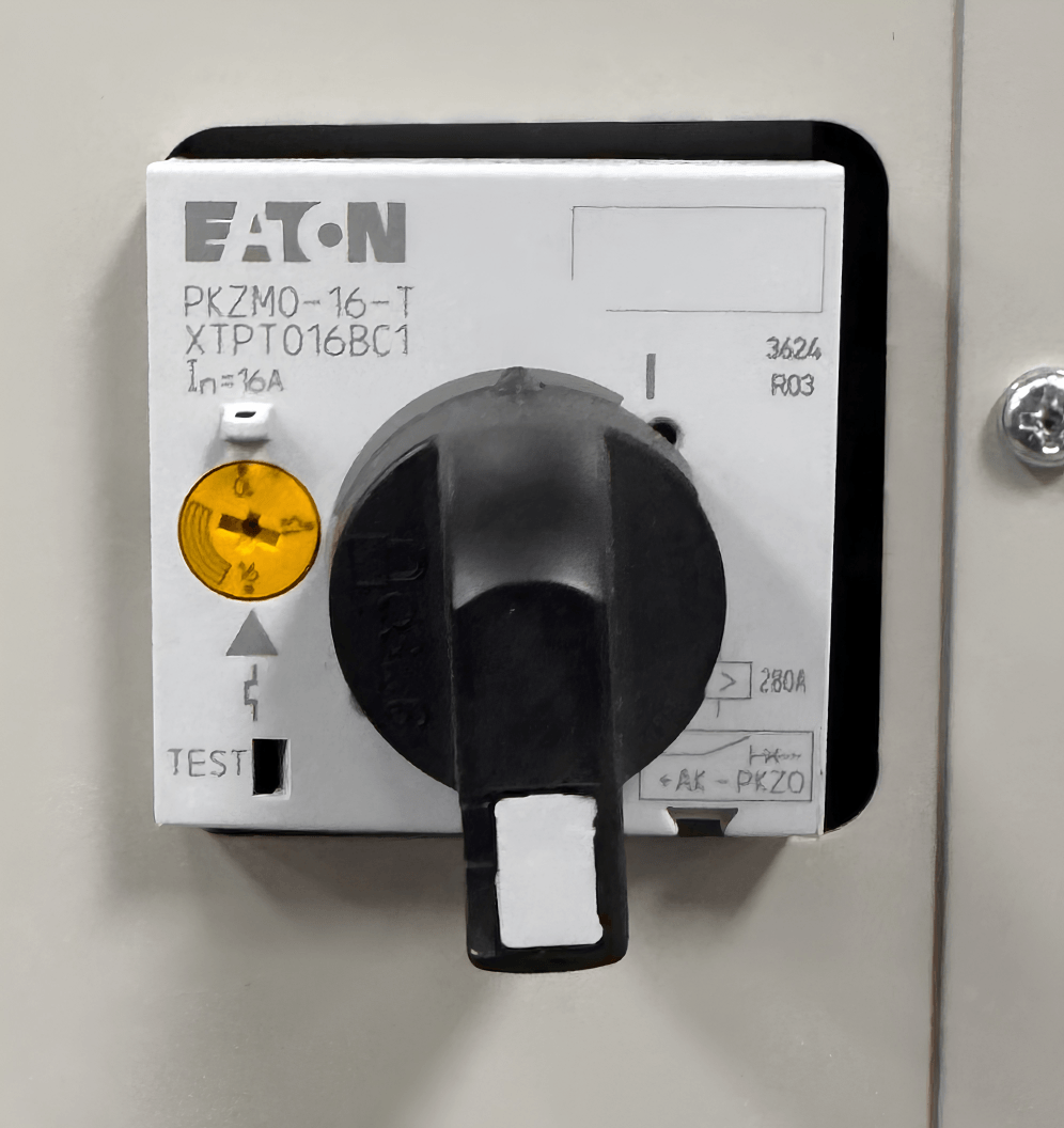 Figure 16: Rotary Breaker for Transformer on CNA11.
Ensure “Local ON/OFF Switch” is in the Off Position. Refer to figure 20.
Ensure “50/60 HZ Toggle Switch” (if equipped) is in the correct position for the power frequency supplied. Refer to figure 20.
Switch the “20A Circuit Breaker” to the “On” position. Refer to figure 20.
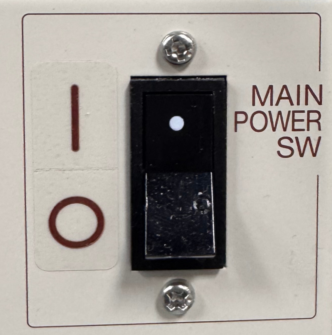 Figure 17: Main Power Switch for CNA11.
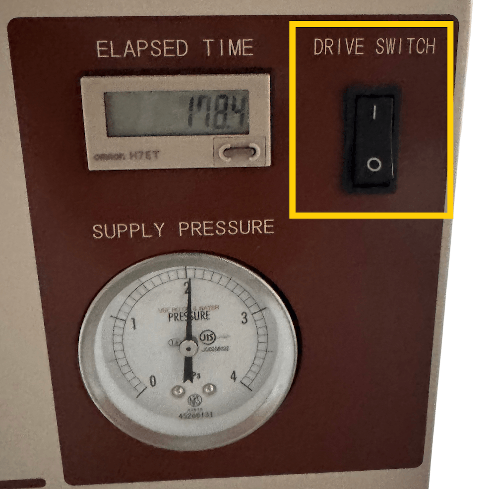 Figure 18: Manual Compressor Drive Switch for CNA11.
Vaccum Pump Installation
Remove the NW25 cap and o-ring from the vacuum port (labeled “Pump/Vent”) loosening the clamp screw and removing the clamp.
Inspect the o-ring to ensure it is dust-free and has no cracks or flaws. If so, replace the o-ring before proceeding.
Using the o-ring and clamp, connect the vacuum pump via the included NW25 vacuum tube to the vacuum port and hand tighten the clamp securely.
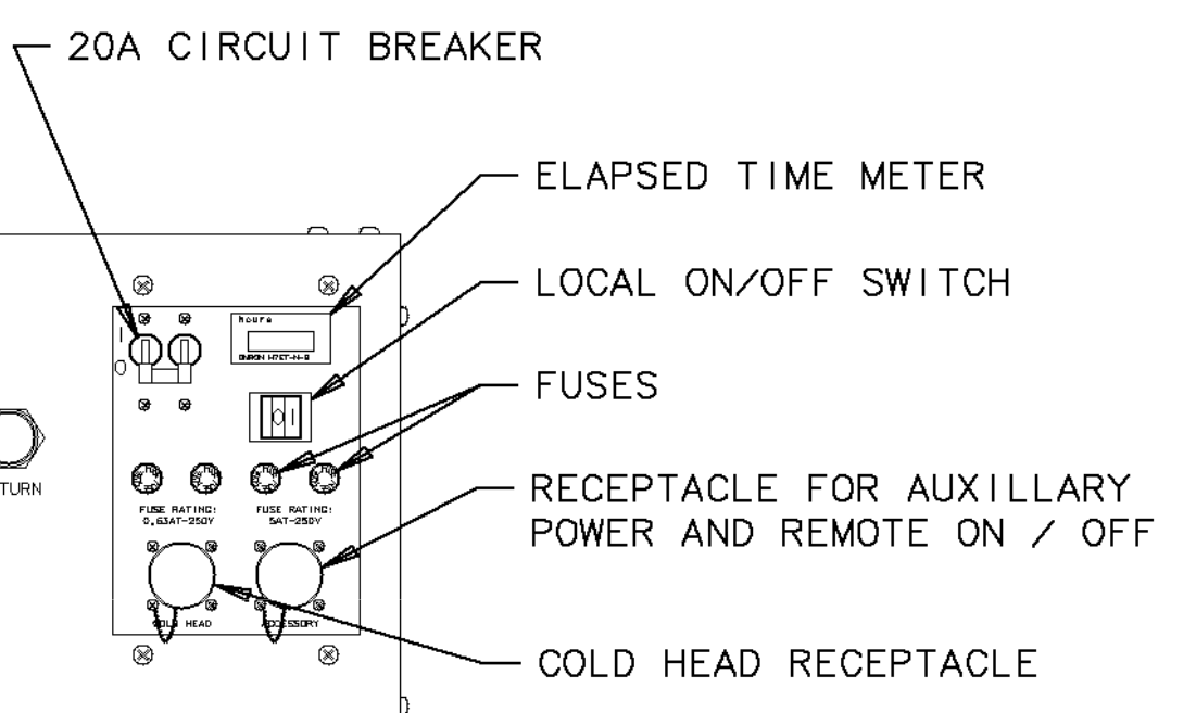 Figure 20: Switches for Water Compressor.
Using the included DB-9 to DC barrel cable, plug in the Vacuum Pump to the Pump Connector on the Opus One The Opus One will now automatically control the vacuum pump as required.
Compressor and Vaccum Pump Setup for Opus One Standard Units
Opus One Standard units require manual user operation of the compressor and vacuum systems. Follow the instructions corresponding to the compressor in use.
For the Air Cooled CNA-11C Compressor
Ensure “Drive Switch” on the front of the compressor is in the Off Position. Refer to
figure 21.Figure 21: Manual Compressor Drive Switch for CNA11.Ensure the “Remote Drive Switch” is in the “INT” Position. Refer to figure 22.
Ensure “Cold Head Drive Switch” is in the “OFF” Position. Refer to figure 22.
Ensure the rotary transformer breaker is rotated to the ON Position. Refer to figure 23.
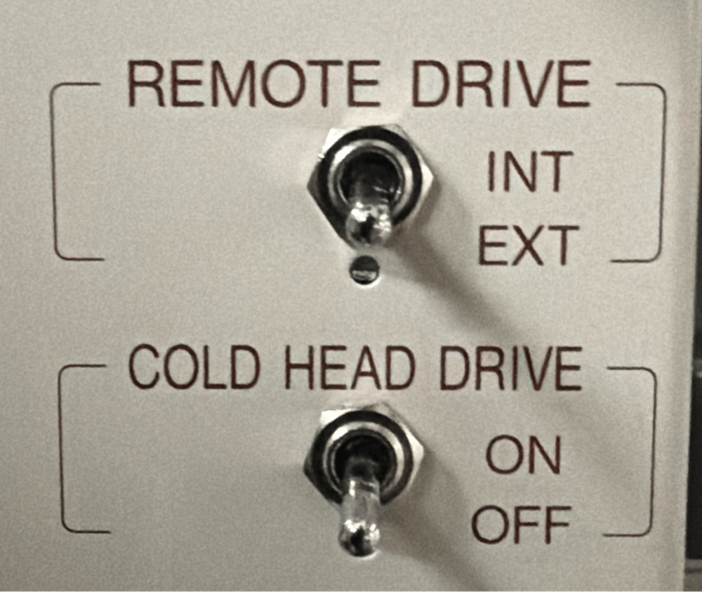 Figure 22: Remote & Cold Head Drive Switches for Air Compressor with standard systemFigure 23: Rotary Breaker for Transformer on CNA11.
Set “Main Power Switch” to the On Position. Refer to figure 24.
Figure 24: Main Power Switch for CNA11.When ready, the “Drive Switch” can be used to power the compressor unit on and off.
For the Water Cooled F20L Compressor
Ensure “Local ON/OFF Switch” is in the Off Position. Refer to figure 25.
Figure 25: Switches for Water Compressor.Ensure “50/60 HZ Toggle Switch” is in the correct position for the power frequency supplied. Refer to figure 25.
Switch the “20A Circuit Breaker” to the “On” position. Refer to figure 25.
When ready, the “Local ON/OFF” can be used to power the compressor unit on and off. Refer to figure 25.
For the Water Cooled HC-4E1 and HC-4E2 Compressor
Ensure “Local ON/OFF Switch” is in the Off Position. Refer to figure 25.
Ensure “50/60 HZ Toggle Switch” (if equipped) is in the correct position for the power
frequency supplied. Refer to figure 25.Switch the “20A Circuit Breaker” to the “On” position. Refer to figure 25.
When ready, the “Local ON/OFF” can be used to power the compressor unit on and off. Refer to figure 25.