
Electronics Unit Installation - For Opus One Standard Only
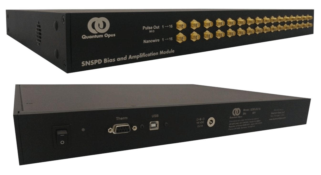
If you have an integrated system, you may skip this section.The stand-alone Quantum Opusnanowire electronics unit is labeled on the front panel “SNSPD Control and Readout Module” or”SNSPD Bias and Amplification Module” and is abbreviated as “QOELEC” in the instructionsbelow. It is seen in Figure 8 on the next page. If your portable unit includes a QOELEC, it isusually placed above the Opus One.
Connecting the electronics to the Opus One
With the QOELEC powered OFF, connect the Opus One to the QOELEC using the provided double-shielded SMA cables. For each detector, connect one cable from the “Nanowire” port on a QOELEC channel to the corresponding “Electrical” SMA connector on the Opus One unit with desired channel number. Tighten the SMA connectors slightly tighter than finger tight using a small SMA wrench (desired torque should be 0.3 to 0.6 N·m, 3 to 5 in·lbs).
Attach the provided 9-pin (DB9 male to DB9 female) filter adapter to the DB9 connector on the back of the QOELEC. Then connect the provided 9-pin cable between the filter and the “Therm” connector on the rear of the Opus One unit.
Connect the provided USB cable between the QOELEC and your computer interface.
Connect the spade connector of the provided ground strap to the grounding terminal on the back of the QOELEC. Use the provided zip ties to strap the free end of the groundingstrap to the stainless tube at the top-rear of the Opus One as seen in Figure 27.
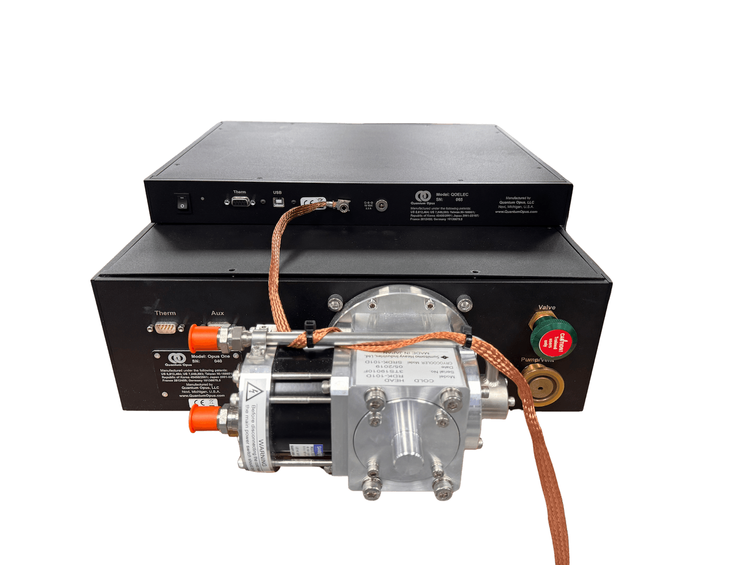 Figure 27: An example grounding strap install.
Plug in the provided power supply to the back of the QOELEC and turn the power on. The power indicator light near the power switch will turn on. The light will be orange if no valid computer connection is made to the unit via USB, and green if a valid connection is made. All connections should be left in place when the QOELEC is powered. Therefore,any changes made to the cabling should be made with the QOELEC powered OFF.